Elements modeled in this environment and their main properties
Any grid2op environment model different elements. In this section, we explain what is modeled and what is not. This page can be usefull:
if you want to better understand an element of grid. For example you don’t really know how to access the “production of a generator”, in this case you can visit the Generators section
or if you are not sure what does “something” refer to. For example, you had a look at the “topo_vect” somewhere, but are not really sure what it means. In this case, you can use the “search” function of your browser (often “ctrl+f”) and search for “topo_vect” that you might find here. For this specific example, you can directly go to Substations.
Note
Grid2Op do not assume any “power system” modeling. The backend is the only one responsible of maintaining the data it generates consistent from a power system point of view.
The “modeling” here is to be understood as “data you can receive, and what they mean” and also time dependencies when it makes sense.
It do not presume anything about any powersystem modeling.
The elements modeled are (work in progress):
Each type of elements will be described in the same way:
Description will present a short description of what is the element
Static properties is the subsection dedicated to the explanation about the properties of the given element that are static (same during all the episode) and acessible from all major grid2op class. For example “gen_pmin” is a static property of the “generators” and it can be accessed with env.gen_pmin, env.action_space.gen_pmin, env.observation_space.gen_pmin, act.gen_pmin or even obs.gen_pmin for example. We do not recommend to alter them.
Modifiable attributes are the attributes than can be modified by the action
Observable attributes are the attributs that can be read from the observation. We do not recommend to alter them.
Equations satisfied explains the “constraint” of all of the above
This page is organized as follow:
Generators
Description
Generators are elements connected to the powergrid who’s role mainly consist in producing prower and maintaining the safety of grid in some conditions (voltage collapse).
An a positive production means the generator produce something, so power is injected from the generator to the grid.
Grid2op implements different information, available at different level that concerns generators. A summary of these information is available in the table below:
Name |
Type |
Described in |
|---|---|---|
n_gen |
int |
static, Static properties |
name_gen |
vect, string |
static, Static properties |
gen_to_subid |
vect, int |
static, Static properties |
gen_to_sub_pos |
vect, int |
(internal) static, Static properties |
gen_pos_topo_vect |
vect, int |
static, Static properties |
* gen_type |
vect, string |
static, Static properties |
* gen_renewable |
vect, bool |
static, Static properties |
* gen_pmin |
vect, float |
static, Static properties |
* gen_pmax |
vect, float |
static, Static properties |
* gen_redispatchable |
vect, bool |
static, Static properties |
* gen_max_ramp_up |
vect, float |
static, Static properties |
* gen_max_ramp_down |
vect, float |
static, Static properties |
* gen_min_uptime |
vect, int |
(currently unused) static, Static properties |
* gen_min_downtime |
vect, int |
(currently unused) static, Static properties |
* gen_cost_per_MW |
vect, float |
(will change in the near future) static, Static properties |
* gen_startup_cost |
vect, float |
(currently unused) static, Static properties |
* gen_shutdown_cost |
vect, float |
(currently unused) static, Static properties |
gen_set_bus |
vect, int |
action, Modifiable attributes |
gen_change_bus |
vect, bool |
action, Modifiable attributes |
redispatch |
vect, float |
action, Modifiable attributes |
curtail |
vect, float |
action, Modifiable attributes |
prod_p |
vect, float |
(internal) action, Modifiable attributes |
prod_v |
vect, float |
(internal) action, Modifiable attributes |
gen_p |
vect, float |
observation, Observable attributes |
gen_q |
vect, float |
observation, Observable attributes |
gen_v |
vect, float |
observation, Observable attributes |
target_dispatch |
vect, float |
observation, Observable attributes |
actual_dispatch |
vect, float |
observation, Observable attributes |
gen_bus |
vect, int |
observation, Observable attributes |
curtailment |
vect, float |
observation, Observable attributes |
gen_p_before_curtail |
vect, float |
observation, Observable attributes |
curtailment_limit |
vect, float |
observation, Observable attributes |
Static properties
Their static properties are:
Name |
Type |
Description |
|---|---|---|
n_gen |
int |
Total number of generators on the grid |
name_gen |
vect, string |
Names of all the generators |
gen_to_subid |
vect, int |
To which substation each generator is connected |
gen_to_sub_pos |
vect, int |
Internal, see Creating a new backend |
gen_pos_topo_vect |
vect, int |
Internal, see Creating a new backend |
* gen_type |
vect, string |
Type of generator, among “nuclear”, “hydro”, “solar”, “wind” or “thermal” |
* gen_renewable |
vect, bool |
Is the generator “renewable” |
* gen_pmin |
vect, float |
Minimum production physically possible for each generator, in MW |
* gen_pmax |
vect, float |
Maximum production physically possible for each generator, in MW |
* gen_redispatchable |
vect, bool |
For each generator, indicates if it can be “dispatched” see the subsection about the action for more information on dispatch |
* gen_max_ramp_up |
vect, float |
For each generator, indicates the maximum values the power can vary (upward) between two consecutive steps in MW. See the subsection about the equations for more information |
* gen_max_ramp_down |
vect, float |
For each generator, indicates the maximum values the power can vary (downward) between two consecutive steps in MW. See the subsection about the equations for more information |
* gen_min_uptime |
vect, int |
(currently unused) For each generator, indicates the minimum time a generator need to be “on” before being turned off. |
* gen_min_downtime |
vect, int |
(currently unused) For each generator, indicates the minimum time a generator need to be “off” before being turned on again. |
* gen_cost_per_MW |
vect, float |
(will change in the near future) Cost of production, in $ / MWh (in theory) but in $ / (MW . step) (each step “costs” prod_p * gen_cost_per_MW) |
* gen_startup_cost |
vect, float |
(currently unused) Cost to turn on each generator (in $) |
* gen_shutdown_cost |
vect, float |
(currently unused) Cost to turn off each generator (in $) |
(* denotes optional properties available only for some environments)
Warning
These attributes are static, and we do not recommend to alter them in any way. They are loaded at the start of the environment and should not be modified.
Static attributes are accessible from most grid2op classes, including, but not limited to : env.n_gen, act.n_gen, obs.n_gen, env.action_space.n_gen, env.observation_space.n_gen
Modifiable attributes
You can modify the generator in different manner, from an action (NB some action do not allow the modification of some of these attributes). Generators can be affected by both continuous and discrete actions.
gen_set_bus: set the bus to which the generator is connected. Usage: act.gen_set_bus = [(gen_id, new_bus)] where gen_id is the id of the generator you want to modify and new_bus the bus to which you want to connect it.
gen_change_bus: change the bus to which the generator is connected. Usage: act.gen_change_bus = gen_id to change the bus of the generator with id gen_id.
redispatch: will apply some redispatching a generator. Usage: act.redispatch = [(gen_id, amount)] to apply a redispatching action of amount MW on generator gen_id
(internal) change the active production of a generator. Usage act.update({“injection”: {“prod_p”: vect}}
(internal) change the voltage setpoint of a generator. Usage act.update({“injection”: {“prod_v”: vect}}
curtail: will apply some curtailment on a generator. Usage: act.curtail = [(gen_id, amount)] to apply a curtailment action of amount on generator gen_id (NB you can also use curtail_MW to apply some curtailment of a certain MW instead of expressing it as a ratio of gen_pmax)
Note
See the Action and in particular the section Main action “properties” for more information about how to manipulate these properties.
Observable attributes
In this section we explain the generators attributes you can access from an observation. These attributes are:
gen_p: the current active production of each generators, in MW. Usage: obs.gen_p[gen_id] will retrieve the active production of generator with id gen_id
gen_q: the current reactive production of each generators, in MVAr. Usage: obs.gen_q[gen_id] will get the reactive production of generator with id gen_id
gen_v: the voltage of the bus at which the generator is connected, in kV. Usage obs.gen_v[gen_id] will get the voltage magnitude of the bus at which generator with id gen_id is connected.
gen_bus: the bus to which each generators is connected. Usage obs.gen_bus[gen_id] will get the bus to which generator with id gen_id is connected (typically -1, 1 or 2).
target_dispatch: the target values given by the agent to the environment (eg using act.redispatch), in MW. Usage: obs.target_dispatch[gen_id]. More information in the “Equations” section.
actual_dispatch: actual dispatch: the values the environment was able to provide as redispatching, in MW. Usage: obs.actual_dispatch[gen_id]. More information in the “Equations” section.
gen_p_before_curtail: give the amount of production for each renewable generators if no curtailment were applied. NB by convention it will be 0.0 for non renewable generator
curtailment: give the ratio of curtailment for each generator. NB it will always be 0.0 for non renewable generator. NB the property curtailment_mw also exists if you want to convert the curtailment, normally expressed in ratio of gen_pmax as a curtailment in MW.
gen_p_before_curtail: give the generation that would occur if there is not curtailment
curtailment_limit: add the limits of all the past curtailment actions. (This is given in ration of gen_pmax, if you want it in MW you can use curtailment_limit_mw)
Satisfied equations
Notations
Let’s denote by:
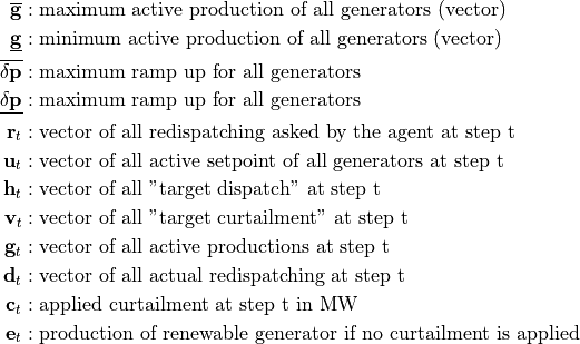
Using the above notation, these vector are accessible in grid2op with:
 = env.gen_pmax
 = env.gen_pmin
 = env.gen_max_ramp_up
 = env.gen_max_ramp_down
 = act.redispatch
 = act.prod_p [typically read from the chronics]
 = obs.target_dispatch
 = act.curtail_mw
 = obs.prod_p [the production in the observation]
 = obs.actual_dispatch
 = obs.curtailment_mw
 = obs.gen_p_before_curtail
Note
Vector are denoted with bold font, like and we will denote the ith component
of this vector with  (here representing then the active production of generator i at step t).
We adopt the same naming convention for all the vectors.
(here representing then the active production of generator i at step t).
We adopt the same naming convention for all the vectors.
NB bold font might not work for some greek letters.
Warning
Unless told otherwise, the letters used here to write the equation are only relevant for the generators.
The same letter is used multiple times for different elements described.
Equations
Generators have limit in the maximum / minimum power they can produce, this entails that:
(1)![\[\forall t, \underline{\mathbf{g}} \leq \mathbf{g}_t \leq \overline{\mathbf{g}}\]](_images/math/79ac4b4e1b569a5cd63f1bbbffdf43fb18d57dbf.png)
Generators are also limited in the maximum / minimum varying power between consecutive steps, this entails that:
(2)![\[\forall t , - \mathbf{\underline{\delta p}} \leq \mathbf{g}_{t+1} - \mathbf{g}_t \leq \mathbf{\overline{\delta p}}\]](_images/math/2568f2138c75f7c808c98d7306fd44f09ca229e9.png)
Non dispatchable generators cannot be dispatched:
(3)![\[\forall t, \forall \text{generator } i, "\text{gen. } i \text{ non dispatchable}" \Rightarrow d^i_t = 0\]](_images/math/fb315d990f4c4bb33290cf2fdea9c1d3db1aa93c.png)
Non renewable generators cannot be curtailed:
(4)![\[\forall t, \forall \text{generator } i, "\text{gen. } i \text{ non renewable}" \Rightarrow c^i_t = 0\]](_images/math/77b24c66f35709d28d47cd62b94a099ada032733.png)
The dispatch actions are added in the “target_dispatch”:
(5)![\[ \forall t,
\left\{
\begin{aligned}
\mathbf{h}_{t+1} &= \mathbf{h}_t + \mathbf{r}_{t+1} \\
&= \sum_{v \leq t+1} \mathbf{r}_{v}
\end{aligned}
\right.
\]](_images/math/945148c577571e0cefbe4a457466f1b30ea1e13c.png)
The total generation is the generation decided by the market (or a central authority) which the agent modified with redispatching (for example because what the market / central authority decided violate some security rules) or by curtailment:
(6)![\[\forall t, \mathbf{g}_t = \mathbf{u}_t + \mathbf{d}_t\]](_images/math/d76c274d297ede65697063960f62296a73fa284f.png)
The production of a renewable generator takes into account the curtailment that will limit its production. So the equation (6) is modified as followed:
(7)![\[ \forall t, \forall i, g^i_t = min \{ v^i_t, g^i_t \} \]](_images/math/b9aa58163b02c3ea60feaf91c64ece1eead66ea5.png)
And it is possible to retrieve the amount of MW that has been “curtailed” with:
(8)![\[ \forall t, \forall i, "\text{gen. } i \text{ non renewable}" \Rightarrow
g^i_t + c^i_t = e^i_t
\]](_images/math/f3e7b7ec7ffd7a2341951b11eace92eacffd9ac0.png)
The redispatching is not supposed to impact the balancing between production and loads, which is supposed to be ensured optimally (if the grid had an infinite capacity, by either a market or a central authority) and neither should this equilibrium be affected by the curtailment. This is why:
(9)![\[\forall t, \sum_{\text{gen } i} d^i_t - \sum_{\text{gen } i} c^i_t = 0\]](_images/math/801e3f5cca4f9b42a38c1e55aac89857813abea6.png)
Compute the redispatching vector
Because the agent do not know , the redispatching action proposed by the agent
 is unlikely to meet equations (1), (2), (6) and
(9). This is why there is a difference between what is actually provided as redispatching
by the environment
is unlikely to meet equations (1), (2), (6) and
(9). This is why there is a difference between what is actually provided as redispatching
by the environment  and what the agent wanted to get .
Currently, the way is computed is by minimizing a distance
(based on the ramps) between the target dispatch “desired by the agent”  and
what is possible to get while satisfying the equations (1), (2), (6) and
(9). The routine to compute this ‘actual dispatch’ uses the
“SLSQP” method of the minimize routine in the scipy.optimize module.
and
what is possible to get while satisfying the equations (1), (2), (6) and
(9). The routine to compute this ‘actual dispatch’ uses the
“SLSQP” method of the minimize routine in the scipy.optimize module.
Note
Equation (9) holds when they are no storage units on the grid. Please see the Storage units (optional) section to get the “constraints” effectively implemented on the grid.
Note
The variable that can be modified wby the optimisation routine are only the turned on dispatchable generators. The other generators (typically solar and ind) but also the storage units, are not modified when solving for this problem.
Loads
Description
A load is an element that consumes power from a powergrid. They are given in the following “sign convention”: if a load is positive, it means power is consumed, if a load is negative it means power is being produced.
Note
In case of a grid interconnected with other grids (as of writing, this is the case for the “l2rpn_neurips_2020_track1” environment), some loads might represent “interconnection powerline”. Basically, we only represent the “side” of each powerline interconnecting the powergrid from “l2rpn_neurips_2020_track1” with another non modeled powergrid as a load. This is why in some cases loads can be negative.
We plan on adding another dedicated element for that in the future, but for now this is how this is.
Grid2op implements different information, available at different level that concerns loads. A summary of these information is available in the table below:
Name |
Type |
Described in |
|---|---|---|
n_load |
int |
static, Static properties |
name_load |
vect, string |
static, Static properties |
load_to_subid |
vect, int |
static, Static properties |
load_to_sub_pos |
vect, int |
(internal) static, Static properties |
load_pos_topo_vect |
vect, int |
(internal) static, Static properties |
load_set_bus |
vect, int |
action, Modifiable attributes |
load_change_bus |
vect, bool |
action, Modifiable attributes |
load_p |
vect, float |
(internal) action, Modifiable attributes |
load_q |
vect, float |
(internal) action, Modifiable attributes |
load_p |
vect, float |
observation, Observable attributes |
load_q |
vect, float |
observation, Observable attributes |
load_v |
vect, float |
observation, Observable attributes |
load_bus |
vect, int |
observation, Observable attributes |
Static properties
Their static properties are:
Name |
Type |
Description |
|---|---|---|
n_load |
int |
Total number of loads on the grid |
name_load |
vect, string |
Names of all the loads |
load_to_subid |
vect, int |
To which substation each load is connected |
load_to_sub_pos |
vect, int |
Internal, see Creating a new backend |
load_pos_topo_vect |
vect, int |
Internal, see Creating a new backend |
(* denotes optional properties available only for some environments)
Warning
These attributes are static, and we do not recommend to alter them in any way. They are loaded at the start of the environment and should not be modified.
Static attributes are accessible from most grid2op classes, including, but not limited to : env.n_load, act.n_load, obs.n_load, env.action_space.n_load, env.observation_space.n_load
Modifiable attributes
You can modify the loads in different manner, from an action (NB some action do not allow the modification of some of these attributes). Loads can be affected by both continuous and discrete actions, though the continous action on loads is for now non accessible to the agent.
load_set_bus: set the bus to which the load is connected. Usage: act.load_set_bus = [(load_id, new_bus)] where load_id is the id of the load you want to modify and new_bus the bus to which you want to connect it.
load_change_bus: change the bus to which the load is connected. Usage: act.load_change_bus = load_id to change the bus of the load with id load_id.
(internal) change the active consumption of a load. Usage act.update({“injection”: {“load_p”: vect}}
(internal) change the reactive consumption of a load. Usage act.update({“injection”: {“load_q”: vect}}
Note
See the Action and in particular the section Main action “properties” for more information about how to manipulate these “properties”.
Observable attributes
In this section we explain the loads attributes you can access from an observation. These attributes are:
load_p: the current active consumption of each load, in MW. Usage: obs.load_p[load_id] will retrieve the active production of load with id load_id
load_q: the current reactive consumption of each load, in MVAr. Usage: obs.load_q[load_id] will get the reactive consumption of load with id load_id
load_v: the voltage of the bus at which the load is connected, in kV. Usage obs.load_v[load_id] will get the voltage magnitude of the bus at which load with id load_id is connected.
load_bus: the bus to which each load is connected. Usage obs.load_bus[load_id] will get the bus to which load with id load_id is connected (typically -1, 1 or 2).
Equations satisfied
The main objective of TSO ( companies operating powergrids) is to make sure the demand is met at all
times. This is why there are no constraints on the loads. Loads can vary as much as they “want”. Agents can only
observe the variation of loads, without being able to perform any intervention on them.
companies operating powergrids) is to make sure the demand is met at all
times. This is why there are no constraints on the loads. Loads can vary as much as they “want”. Agents can only
observe the variation of loads, without being able to perform any intervention on them.
Note
More recently, some “new” methods have been developed that could allow TSO, to some extend, to have some control on the demand. These methods, known as “demand side management” are not available yet in grid2op. Do not hesitate to fill a “feature request” if this topic is relevant for you.
Powerlines
Description
Powerlines are “elements” of the grid that allow the power to flow from one part of the grid to another. They are connecting two different substations.
In grid2op, a powerline is represented by two side: an “origin” side, in the *_line_or_* vectors and an “extremity” side whose information will be given in the *_line_ex_* vectors.
One of the main objective of TSO, in real time, is to make sure the flows on the powerline do not exceed its capacity.
In grid2op, two “maximum capacties” are modeled. Grid2op will (depending on the
Parameters.Parameters used) disconnect automatically powerlines:
if there are on overflow for too long (known as “time overcurrent (TOC)” see this article for more information overcurrent ) Conceptually this means the environment remember for how long a powergrid is in “overflow” and disconnects it if needed. NB This is an emulation of what happen on the grid, in case you use a Backend that do not have this feature (for example if you use static / steady state powerflow). This emulation might not be necessary (and less “realistic” if you use a time domain simulator)
if the overflow is too high (known as “instantaneous overcurrent” see the same wikipedia article). This means from one step to another, a given powerline can be disconnected if too much flow goes through it. NB This is an emulation of what happen on the grid, in case you use a Backend that do not have this feature (for example if you use static / steady state powerflow). This emulation might not be necessary (and less “realistic” if you use a time domain simulator)
Grid2op implements different information, available at different level that concerns loads. A summary of these information is available in the table below:
Name |
Type |
Described in |
|---|---|---|
n_line |
int |
static, Static properties |
name_line |
vect, string |
static, Static properties |
line_or_to_subid |
vect, int |
static, Static properties |
line_ex_to_subid |
vect, int |
static, Static properties |
line_or_to_sub_pos |
vect, int |
static, Static properties |
line_ex_to_sub_pos |
vect, int |
static, Static properties |
line_or_pos_topo_vect |
vect, int |
static, Static properties |
line_ex_pos_topo_vect |
vect, int |
static, Static properties |
line_or_set_bus |
vect, int |
action, Modifiable attributes |
line_ex_set_bus |
vect, int |
action, Modifiable attributes |
line_ex_change_bus |
vect, int |
action, Modifiable attributes |
line_or_change_bus |
vect, int |
action, Modifiable attributes |
line_set_status |
vect, int |
action, Modifiable attributes |
line_change_status |
vect, int |
action, Modifiable attributes |
a_or |
vect, float |
observation, Observable attributes |
a_ex |
vect, float |
observation, Observable attributes |
p_or |
vect, float |
observation, Observable attributes |
p_ex |
vect, float |
observation, Observable attributes |
q_or |
vect, float |
observation, Observable attributes |
q_ex |
vect, float |
observation, Observable attributes |
v_or |
vect, float |
observation, Observable attributes |
v_ex |
vect, float |
observation, Observable attributes |
rho |
vect, float |
observation, Observable attributes |
line_status |
vect, bool |
observation, Observable attributes |
timestep_overflow |
vect, int |
observation, Observable attributes |
time_before_cooldown_line |
vect, int |
observation, Observable attributes |
time_next_maintenance |
vect, int |
observation, Observable attributes |
duration_next_maintenance |
vect, int |
observation, Observable attributes |
thermal_limit |
vect, float |
observation, Observable attributes |
line_or_bus |
vect, int |
observation, Observable attributes |
line_ex_bus |
vect, int |
observation, Observable attributes |
Note
A “grid2op powerlines” includes both “powerlines” and “transformers” in power system terminology. For grid2op, transformers are powerlines.
Static properties
Their static properties are:
Name |
Type |
Description |
|---|---|---|
n_line |
int |
Total number of lines on the grid |
name_line |
vect, string |
Names of all the lines |
line_or_to_subid |
vect, int |
To which substation each line (origin side) is connected |
line_ex_to_subid |
vect, int |
To which substation each line (extremity side) is connected |
line_or_to_sub_pos |
vect, int |
Internal, see Creating a new backend |
line_ex_to_sub_pos |
vect, int |
Internal, see Creating a new backend |
line_or_pos_topo_vect |
vect, int |
Internal, see Creating a new backend |
line_ex_pos_topo_vect |
vect, int |
Internal, see Creating a new backend |
(* denotes optional properties available only for some environments)
Warning
These attributes are static, and we do not recommend to alter them in any way. They are loaded at the start of the environment and should not be modified.
Static attributes are accessible from most grid2op classes, including, but not limited to : env.n_line, act.n_line, obs.n_line, env.action_space.n_line, env.observation_space.n_line
Modifiable attributes
You can modify the powerlines in different manner, from an action (NB some action do not allow the modification of some of these attributes). Powerlines can be affected only by discrete actions.
line_or_set_bus: set the bus to which the origin side of the powerline is connected. Usage: act.line_or_set_bus = [(line_id, new_bus)] where line_id is the id of the line (origin side) you want to modify and new_bus the bus to which you want to connect it.
line_ex_set_bus: set the bus to which the extremity side of the powerline is connected. Usage: act.line_ex_set_bus = [(line_id, new_bus)] where line_id is the id of the line (extremity side) you want to modify and new_bus the bus to which you want to connect it.
line_or_change_bus: change the bus to which the origin side of a powerline is connected. Usage: act.line_or_change_bus = line_id to change the bus of the origin side of line with id line_id is connected
line_ex_change_bus: change the bus to which the extremity side of a powerline is connected. Usage: act.line_ex_change_bus = line_id to change the bus of the extremity side of line with id line_id is connected
line_set_status: set the status (connected / disconnected) of a powerline. Usage: act.line_set_status = [(line_id, new_status)] where line_id is the id of the powerline you want to modify, and new_status (-1 or 1) is the the new target status. (NB when a powerline is disconnected, both its “origin side” and “extremity side” are also disconnected)
line_change_status: change the status of a powerline. Usage: act.line_change_status = line_id where line_id is the id of the powerline you want to modify.
Note
See the Action and in particular the section Main action “properties” for more information about how to manipulate these properties.
Observable attributes
Lots of information concerning powerlines are available in the observation:
a_or: intensity flows (also known as current flows) at the “origin side” of the powerlines, measured in Amps (A). Usage: obs.a_or[line_id].
a_ex: intensity flows (also known as current flows) at the “extremity side” of the powerlines, measured in Amps (A). Usage: obs.a_ex[line_id].
p_or: active flows at the “origin side” of the powerlines, measured in Mega Watt (MW). Usage: obs.p_or[line_id].
p_ex: active flows at the “extremity side” of the powerlines, measured in Mega Watt (MW). Usage: obs.p_ex[line_id].
q_or: reactive flows at the “origin side” of the powerlines, measured in Mega Volt Amps reactive (MVAr). Usage: obs.q_or[line_id].
q_ex: reactive flows at the “extremity side” of the powerlines, measured in Mega Volt Amps reactive (MVAr). Usage: obs.q_ex[line_id].
v_or: voltage magnitude at the bus to which the “origin side” of the powerline is connected, measured in kilo Volt (kV). Usage: obs.v_or[line_id].
v_ex: voltage magnitude at the bus to which the “extremity side” of the powerline is connected, measured in kilo Volt (kV). Usage: obs.v_ex[line_id].
rho: relative flows on each powerlines. It is the ratio of the flow on the powerline divided by its thermal limit. It has no unit (usually between 0. and 1.0. When the powerline is on overflow, then rho > 1.0) Usage: obs.rho[line_id].
line_status: gives the status (connected / disconnected) of each powerlines. This is a vector of boolean. Usage: obs.line_status[line_id].
timestep_overflow: for each powerline, returns the number of steps since this powerline is on overflow. This is given in number of steps (no units). Most of the time it will be 0 meaning the powerline is not on overflow. When there is an overflow, this number will increase. If it exceeds
grid2op.Parameters.Parameters.NB_TIMESTEP_OVERFLOW_ALLOWEDthen the powerline is automatically disconnected by the environment. Usage: obs.timestep_overflow[line_id].time_before_cooldown_line: number of steps you need to wait before being able to change the status of powerline again. It is usually 0, but if if obs.time_before_cooldown_line[line_id] > 0 you cannot do an action that will affect the status of a powerline (this action will be illegal). Usage: obs.time_before_cooldown_line[line_id].
time_next_maintenance: indicates the next scheduled maintenance operation on each of the powerline. See the description given in
grid2op.Observation.BaseObservation.time_next_maintenancefor more information. Usage: obs.time_next_maintenance[line_id].duration_next_maintenance: indicates the duration of the next scheduled maintenance for each powerline. See the description given in
grid2op.Observation.BaseObservation.duration_next_maintenancefor more information. Usage: obs.duration_next_maintenance[line_id].thermal_limit: for each powerline, it gives its “thermal limit” (eg maximum intensity allowed on the powerline). Usage: obs.thermal_limit[line_id].
line_or_bus: for each powerline, it gives the busbars (usually -1, 1 or 2) at which the “origin side” of the powerline is connected. Usage: obs.line_or_bus[line_id].
line_ex_bus: for each powerline, it gives the busbars (usually -1, 1 or 2) at which the “extremity side” of the powerline is connected. Usage: obs.line_ex_bus[line_id].
Note
By default, in most grid2op environments, the “Backend” will use an AC modeling of the powergrid. This means that losses are taken into account, so most of the time, obs.p_or + obs.p_ex will not be 0.00.
The losses also explains why obs.a_or and obs.a_ex are not equal (for “real powerline”). They are often slightly different.
Note
By default, thermal limit are computed on the “origin side” of the powerlines. This means that obs.a_ex can exceed the thermal limits.
Satisfied equations
In this section, as opposed to the equivalent description of the generators or the storage units, we will not write any equations. Introducing new notation made this section really unclear and we found that explaining the concept in english to be more efficient.
Here are the attributes affected by one or more “constraints” on grid2op:
act.line_set_status and act.line_change_status:
it is not possible to change the status of a powerline too regularly. See the description of
grid2op.Parameters.Parameters.NB_TIMESTEP_COOLDOWN_LINEfor more information.at a given step, it is not possible to change the status of too many powerlines. This parameters is set in
grid2op.Parameters.Parameters.MAX_LINE_STATUS_CHANGED(NB this is not affected by maintenance or hazards nor by any modification made automatically by the environment)when a powerline is connected for safety reasons, you have to wait for a certain number of steps before being able to reconnect it again (see
grid2op.Parameters.Parameters.NB_TIMESTEP_RECONNECTION)when a powerline is “under attack” or there is a maintenance happening, this powerline will stay disconnected for a given number of steps available in obs.duration_next_maintenance or obs.time_before_cooldown_line
obs.a_or (sometimes also obs.a_ex): the flows on a powerline cannot exceed the obs.thermal_limit for too long neither become too high (see also
grid2op.Parameters.Parameters.NO_OVERFLOW_DISCONNECTIONto deactivate this behaviour):the maximum number of consecutive steps a powerline can be on overflow is set in
grid2op.Parameters.Parameters.NB_TIMESTEP_OVERFLOW_ALLOWEDthe threshold above which a line is instantly disconnected is given in
grid2op.Parameters.Parameters.HARD_OVERFLOW_THRESHOLD
Note
If the flow on a powerline falls below the thermal limit for a given step, then it will reset the obs.timestep_overflow to 0. for this powerline, even if this does not last for long. It is then possible to “play” with this feature to prevent the disconnection of powerlines (disconnect it “manually” just before the protections works and reconnect if as soon as possible). This is considered (very) bad practice for real time operations though.
Shunts (optional)
Description
TODO
Static properties
Their static properties are:
Name |
Type |
Description |
|---|---|---|
TODO |
(* denotes optional properties available only for some environments)
Warning
These attributes are static, and we do not recommend to alter them in any way. They are loaded at the start of the environment and should not be modified.
Modifiable attributes
TODO
Note
See the Action and in particular the section Main action “properties” for more information about how to manipulate these properties.
Observable attributes
TODO
Satisfied equations
TODO
Storage units (optional)
Description
Storage units are units that can act both as a production or a load. They have typically a certain maximum energy the can store (when they are storing they take power from the grid to store it) that can be discharge at any moment for a certain period (providing a certain maximum power for a given period of time).
In grid2op, storage units have the load convention:
a positive power means they are charging and thus absorb power from the grid (behaving like load)
a negative power means they are discharging, and thus inject power to the grid (behaving like generator)
These storage units represents facilities that can store power in an industrial fashion. They are typically pumped storage or batteries for example.
Some inspiration for the modeling of the storage units were provided by the NREL document: https://www.greeningthegrid.org/news/new-resource-grid-scale-battery-storage-frequently-asked-questions-1
Grid2op implements different information, available at different level that concerns storage units. A summary of these information is available in the table below:
Name |
Type |
Described in |
|---|---|---|
n_storage |
int |
static, Static properties |
name_storage |
vect, str |
static, Static properties |
storage_to_subid |
vect, int |
static, Static properties |
storage_to_sub_pos |
vect, int |
static, Static properties |
storage_pos_topo_vect |
vect, int |
static, Static properties |
storage_type |
vect, str |
static, Static properties |
storage_Emax |
vect, float |
static, Static properties |
storage_Emin |
vect, float |
static, Static properties |
storage_max_p_prod |
vect, float |
static, Static properties |
storage_max_p_absorb |
vect, float |
static, Static properties |
storage_marginal_cost |
vect, float |
static, Static properties |
storage_loss |
vect, float |
static, Static properties |
storage_charging_efficiency |
vect, float |
static, Static properties |
storage_discharging_efficiency |
vect, float |
static, Static properties |
storage_set_bus |
vect, int |
action, Modifiable attributes |
storage_change_bus |
vect, int |
action, Modifiable attributes |
storage_p |
vect, float |
action, Modifiable attributes |
storage_power |
vect, float |
observation, Observable attributes |
storage_power_target |
vect, float |
observation, Observable attributes |
storage_charge |
vect, float |
observation, Observable attributes |
storage_bus |
vect, float |
observation, Observable attributes |
Static properties
Their static properties are:
Name |
Type |
Description |
|---|---|---|
n_storage |
int |
Number of storage units on the grid |
name_storage |
vect, str |
Name of each storage units |
storage_to_subid |
vect, int |
Id of the substation to which each storage units is connected |
storage_to_sub_pos |
vect, int |
Internal, see Creating a new backend |
storage_pos_topo_vect |
vect, int |
Internal, see Creating a new backend |
storage_type |
vect, str |
Type of storage, among “battery” or “pumped_storage” |
storage_Emax |
vect, float |
For each storage unit, the maximum energy it can contains, in MWh |
storage_Emin |
vect, float |
For each storage unit, the minimum energy it can contains, in MWh |
storage_max_p_prod |
vect, float |
For each storage unit, the maximum power it can give to the grid, in MW |
storage_max_p_absorb |
vect, float |
For each storage unit, the maximum power it can take from the grid, in MW |
storage_marginal_cost |
vect, float |
For each storage unit, the cost for taking / adding 1 MW to the grid, in $ |
storage_loss |
vect, float |
For each storage unit, the self discharge, in MW, of the unit |
storage_charging_efficiency |
vect, float |
For each storage unit, the “charging efficiency” (see bellow) |
storage_discharging_efficiency |
vect, float |
For each storage unit, the “discharging efficiency” (see bellow) |
(* denotes optional properties available only for some environments)
The storage_charging_efficiency is a float between 0. and 1. If it’s 1.0 it means that if the storage unit absorb 1MW from the grid during 1h period, then 1MWh are added to the state of charge. If this efficiency is 0.5 then if 1MW is absorbed by the storage unit from the grid then only 0.5MWh will be stored in the unit.
It works symmetrically for storage_discharging_efficiency. For a storage unit, having a storage_discharging_efficiency of 0.5 means that if the unit provide 1MW to the grid for 1h, then its state of charge has been reduced by 2MWh (it would have been reduced by only 1MWh if this efficiency was 1.0).
Warning
These attributes are static, and we do not recommend to alter them in any way. They are loaded at the start of the environment and should not be modified.
Static attributes are accessible from most grid2op classes, including, but not limited to : env.n_storage, act.n_storage, obs.n_storage, env.action_space.n_storage, env.observation_space.n_storage
Modifiable attributes
You can modify the generator in different manner, from an action (NB some action do not allow the modification of some of these attributes).
storage_set_bus: set the bus to which the storage unit is connected. Usage: act.storage_set_bus = [(stor_id, new_bus)] where stor_id is the id of the storage unit you want to modify and new_bus the bus to which you want to connect it.
storage_change_bus: change the bus to which the storage unit is connected. Usage: act.storage_change_bus = stor_id to change the bus of the storage unit with id stor_id.
storage_p: will tell the storage unit you want to get a given amount of power on the grid. Usage: act.storage_p = [(stor_id, amount)] to tell the storage unit stor_id to produce / absorb amount MW for the grid for the next step.
Note
See the Action and in particular the section Main action “properties” for more information about how to manipulate these properties.
Observable attributes
In this section we explain the storage unit attributes you can access from an observation. These attributes are:
storage_charge: the state of charge of each storage unit, in MWh. Usage: obs.storage_charge[sto_id]
storage_power_target: the power that was required from the last action of the agent, in MW
storage_power: the power that is actually produced / absorbed by every storage unit.
storage_bus: for each storage unit, it gives the busbars (usually -1, 1 or 2) at which it is connected.
Satisfied equations
Notations
Let’s denote by:
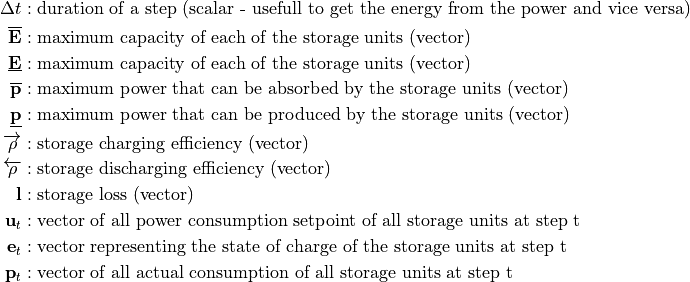
Using the above notation, these vector are accessible in grid2op with:
 = env.storage_Emax
 = env.storage_Emin
 = env.storage_max_p_absorb
 = env.storage_max_p_prod
 = env.storage_charging_efficiency
 = env.storage_discharging_efficiency
 = env.storage_loss
- = act.storage_p [the production / consumption setpoint, in the action]
 = obs.storage_power [the actual production / consumption, in the observation]
- = obs.storage_charge
Note
Vector are denoted with bold font, like and we will denote the ith component
of this vector with  (here representing then the active state of charge of
storage unit i at step t).
We adopt the same naming convention for all the vectors.
(here representing then the active state of charge of
storage unit i at step t).
We adopt the same naming convention for all the vectors.
NB bold font might not work for some greek letters.
Warning
Unless told otherwise, the letters used here to write the equation are only relevant for the generators.
It can happen the same letter is used multiple times for different element.
Equations
In any case, the charge cannot be negative, and cannot be above the maximum (no there is not error here, in some cases, the state of charge can appear to be slightly below the minimum, because of the losses):
(10)![\[\forall t, 0 \leq \mathbf{e}_t \leq \overline{\mathbf{E}} \]](_images/math/6928524ed9b0477730bdbf68d9b2e9e0ed34eb09.png)
The storage charging / discharging equations are (keep in mind these are not the production / consumption setpoint given in the action, but the production / setpoint available in the observation):
(11)![\[ \forall \text{step } t, \forall \text{storage units } j,
\left\{
\begin{aligned}
\text{if } p^j_t > 0, & e^j_t = e^j_t + \overrightarrow{\rho} . p^j_t . \Delta t & \text{ battery is charging} \\
\text{if } p^j_t < 0, & e^j_t = e^j_t + \frac{1.0}{\overleftarrow{\rho}} . p^j_t . \Delta t & \text{ battery is discharging}
\end{aligned}
\right.
\label{eq:charging}
\]](_images/math/0dcdec39e668f61bd2859917cf30fd004a70a901.png)
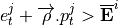
There is a difference between the power setpoint and the actual implementation, mainly because there are
some constraint in the total amount of energy that can be stored in the unit. This translates into
a difference between the implemented storage production / consumption and a the
setpoint in the action :
(12)![\[
\begin{aligned}
\min_{\mathbf{p}_t} & \left|\left| \mathbf{p}_t - \mathbf{u}_t \right|\right| \\
\text{s.t.} & \\
& \text{if } p^j_t > 0, e^i_t + \overrightarrow{\rho} . p^j_t . \Delta t \leq \overline{\mathbf{E}}^i \\
& \text{if } p^j_t < 0, e^i_t + \frac{1.0}{\overleftarrow{\rho}} . p^j_t . \Delta t \geq \underline{\mathbf{E}}^i
\end{aligned}
\]](_images/math/a023db4c2e57938182ec30fdd87b3827f43a3cd3.png)
Currently this problem is not solved using an optimisation routine, but rather, if one of the constraints of
the (12) is not met then the action is caped at the right value (eg if
 for one
  then
solving for
then
solving for  the equation
 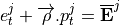 )
)
As for the redispatching, the modification of the storage production / consumption is not supposed to impact the balancing between production and loads, which is ensured by “the market” (or a central authority). This means that, in case of presence of storage unit, the (9) showed in the Generators is modified as followed:
(13)![\[\forall t, \sum_{\text{gen } i} d^i_t - \sum_{\text{gen } i} c^i_t + \sum_{\text{storage } j} p^j_t = 0\]](_images/math/591a83611f09259e331b3b839bf28f074a31fa61.png)
In the current implementation, this is done by substuting the equation (13) instead of equation (9) when solving the optimization routine detailed in Compute the redispatching vector. The storage units are NOT modified by this optimization routine.
Last, but not least, the storage loss is taken into account as followed:
(14)![\[\forall t, \mathbf{e}_{t+1} = \mathbf{e}_{t} - \mathbf{l}.\Delta t \]](_images/math/cfff794247c343b3804ba8738964daa5251bc7bb.png)
The equation (14) supposes that  has been updated with the equations
(10), (11), (12) and (13) (this means that we do not,
for clarity, added “temporary” notations for the results of each computations in
(10), (11), (12) and (13), which would have been more rigourous
but harder to read)
has been updated with the equations
(10), (11), (12) and (13) (this means that we do not,
for clarity, added “temporary” notations for the results of each computations in
(10), (11), (12) and (13), which would have been more rigourous
but harder to read)
Note
This is why, in the observation, you can get a “state of charge” (obs.storage_charge,
) below obs.storage_Emin (aka ) because of the losses.
If that is the case at one step, even if no action is done by the agent, then some power will be taken from the grid to charge the storage unit until its “minimum capacity” is met.
When this happens, the storage charge will remain unchanged (and slightly below obs.storage_Emin) but some “infinite” amount of power will be taken from the grid to the storage unit. This is consistent with reality: you would need to keep the battery charged to compensate for the losses if you want to maintain it a given charge.
This phenomenon explains that the losses should be lower than the maximum charging capacity of the storage units. Otherwise, the storage would be “doomed” to be discharged and nothing could be done about it, which would make a relatively uninteresting unit for “real” grid.
Substations
Description
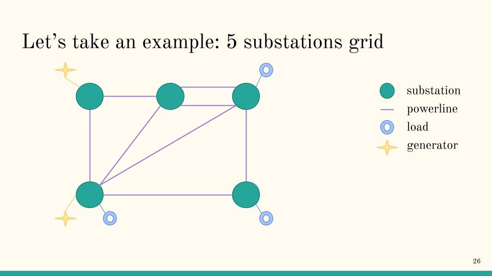
A “substation” is a place (that exists, you can touch it) where “elements” (side of a powerline, a load, a generator or a storage unit) belonging to the powergrid are connected all together.
Substations are connected to other substation with powerlines (this is why powerline have two “sides”: one for each substation they are connecting).
In most powergrid around the world, substations are made of multiple “busbars”. In grid2op we supposes that every “elements” connected to a substation can be connected to every busbars in the substation. This is mainly done for simplicity, for real powergrid it might not be the case.
In earlier grid2op versions, we also assumed that, for simplicity, each substations counts exactly 2 distincts busbars. Starting from grid2op 1.9.9, it is possible when you create an environment, to specify how many busbars are available in each substation. You can customize it with:
import grid2op
env_name = "l2rpn_case14_sandbox"

env_2_busbars = grid2op.make(env_name)  # default
env_2_busbars_bis = grid2op.make(env_name, n_busbar=2)  # same as above

# one busbar
env_1_busbar = grid2op.make(env_name, n_busbar=1)
#NB: topological action on substation (set_bus, change_bus) are not possible in this case !

# 3 busbars
env_3_busbars = grid2op.make(env_name, n_busbar=3)
#NB: "change_bus" type of actions are not possible (it would be ambiguous - non unique-
#    on which busbar you want to change them)

# 10 busbars
env_10_busbars = grid2op.make(env_name, n_busbar=10)
#NB: "change_bus" type of actions are not possible (it would be ambiguous - non unique-
#    on which busbar you want to change them)
At the initial step (right after env.reset()), for all environment available at the time of writing (february 2021) every objects were connected to the busbar 1 of their substation. This is not a requirement of grid2op, but it was the case for every environments created.
Rephrasing the topology control problem
Here is a representation of a powergrid with 5 substations:
The “graph of the grid” can be represented as a vector, given, for each element whether the element is connected at busbar 1 or busbar 2. This can be done by assigning to each “element” of the grid a “component” of the “topology vector”. This “component” will then encode whether this “element” is connected to busbar 1 or busbar 2. For example, if everything is connected at busbar 1, we get the following representation
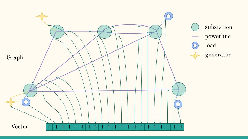
(we denoted arrow to explicitly map the “element” of the grid, to its corresponding component of the vector)
Now, as an example let’s consider we modify the busbar at which 2 elements were connected, this gives the following representation
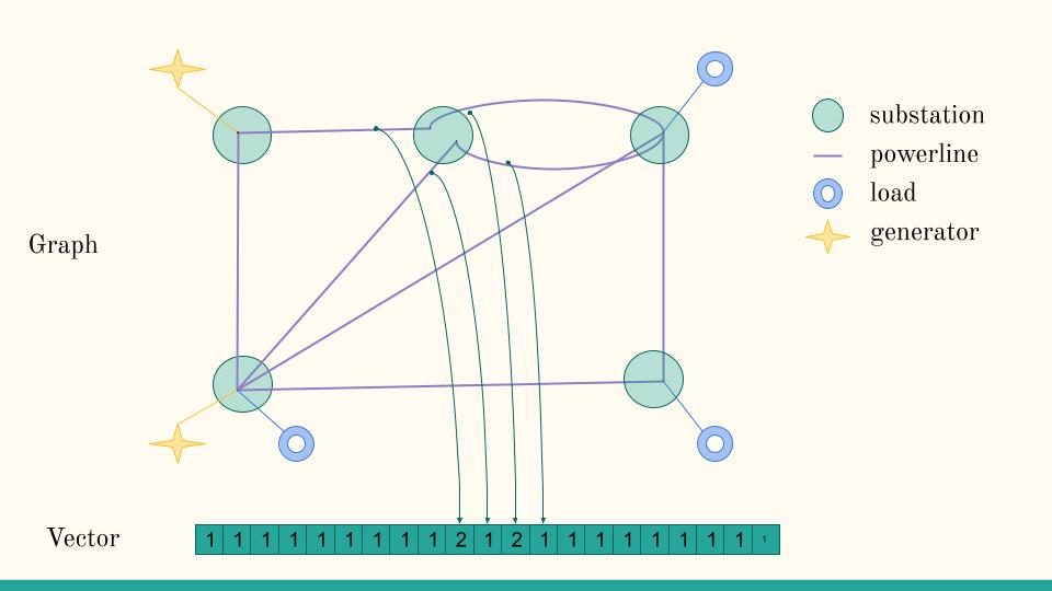
As you can see, in this example, the number of “nodes” in the graph is affected. Originally there were 5 “nodes” on the graph, but after setting to “busbar 2” two elements, there is 6. Indeed, as we can see on substation 2 above, there 2 independent nodes (“buses”) on this last image, whereas there is only 1
The set of problems tackled in grid2op are then to find the best “topology vector” (a specific representation of the powergrid, as explained in this paragraph) such that the contraints exposed on eg in paragraph “Satisfied equations” of the “Lines” section are met at any times.
Note
If two objects are not connected to the same substation, they cannot be connected together.
Attributes of the substations
Grid2op implements different information, available at different level that concerns the substations. A summary of these information is available in the table below:
Name |
Type |
Described in |
|---|---|---|
n_sub |
int |
static, Static properties |
sub_info |
vect, int |
static, Static properties |
dim_topo |
int |
static, Static properties |
name_sub |
vect, str |
static, Static properties |
set_bus |
vect, int |
action, Modifiable attributes |
change_bus |
vect, int |
action, Modifiable attributes |
topo_vect |
vect, int |
observation, Observable attributes |
time_before_cooldown_sub |
vect, int |
observation, Observable attributes |
Static properties
Their static properties are:
Name |
Type |
Description |
|---|---|---|
n_sub |
int |
Total number of substation on the grid |
sub_info |
vect, int |
For each substations, gives the number of elements (side of powerline, load, generator or storage unit) connected to it. |
dim_topo |
int |
Total number of elements (side of powerline, load, generator or storage unit) on the grid |
name_sub |
vect, str |
Name of each substation |
(* denotes optional properties available only for some environments)
Warning
These attributes are static, and we do not recommend to alter them in any way. They are loaded at the start of the environment and should not be modified.
Static attributes are accessible from most grid2op classes, including, but not limited to : env.n_sub, act.n_sub, obs.n_sub, env.action_space.n_sub, env.observation_space.n_sub
Modifiable attributes
These are the attribute of the action you can use to affect the substation. The substation can be only affected by discrete action for the moment.
set_bus: perform an action of type set_bus on a given set of elements. Usage: act.set_bus = [(el_id, new_bus)] to set the bus of the element with id el_id to new_bus (typically new_bus is -1, 1 or 2)
change_bus: perform an action of type change_bus on a given set of elements. Usage: act.set_bus = [el_id]
Note
See the Action and in particular the section Main action “properties” for more information about how to manipulate these properties.
Links with the ***_set_bus
In this paragraph, we explain the links there are between the act.set_bus and the act.line_or_set_bus, act.line_ex_set_bus, act.load_set_bus, act.gen_set_bus or act.storage_set_bus.
Basically it works the same way, and all of the above allows to do the same thing, albeit a bit differently.
Originally, only the act.set_bus was present and the others were added for convenience. Basically:
act.line_or_set_bus = [(line_id, new_bus)] is exactly equivalent to act.set_bus = [(act.line_or_pos_topo_vect[line_id], new_bus)] and we also have: act.line_ex_set_bus == act.set_bus[act.line_or_pos_topo_vect]
act.line_ex_set_bus = [(line_id, new_bus)] is exactly equivalent to act.set_bus = [(act.line_ex_pos_topo_vect[line_id], new_bus)] and we also have: act.line_ex_set_bus == act.set_bus[act.line_ex_pos_topo_vect]
act.load_set_bus = [(load_id, new_bus)] is exactly equivalent to act.set_bus = [(act.load_pos_topo_vect[load_id], new_bus)] and we also have: act.load_set_bus == act.set_bus[act.load_pos_topo_vect]
act.gen_set_bus = [(gen_id, new_bus)] is exactly equivalent to act.set_bus = [(act.gen_pos_topo_vect[gen_id], new_bus)] and we also have: act.gen_set_bus == act.set_bus[act.gen_pos_topo_vect]
act.storage_set_bus = [(storage_id, new_bus)] is exactly equivalent to act.set_bus = [(act.storage_pos_topo_vect[storage_id], new_bus)] and we also have: act.storage_set_bus == act.set_bus[act.storage_pos_topo_vect]
Links with the ***_change_bus
It is exactly the same behaviour as described in the section above, for exactly the same reason. We have:
act.line_or_change_bus = [line_id] is exactly equivalent to act.change_bus = [act.line_or_pos_topo_vect[line_id]] and we also have: act.line_ex_change_bus == act.change_bus[act.line_or_pos_topo_vect]
act.line_ex_change_bus = [line_id] is exactly equivalent to act.change_bus = [act.line_ex_pos_topo_vect[line_id]] and we also have: act.line_ex_change_bus == act.change_bus[act.line_ex_pos_topo_vect]
act.load_change_bus = [load_id] is exactly equivalent to act.change_bus = [act.load_pos_topo_vect[load_id]] and we also have: act.load_change_bus == act.change_bus[act.load_pos_topo_vect]
act.gen_change_bus = [gen_id] is exactly equivalent to act.change_bus = [act.gen_pos_topo_vect[gen_id]] and we also have: act.gen_change_bus == act.change_bus[act.gen_pos_topo_vect]
act.storage_change_bus = [storage_id] is exactly equivalent to act.change_bus = [act.storage_pos_topo_vect[storage_id]] and we also have: act.storage_change_bus == act.change_bus[act.storage_pos_topo_vect]
Observable attributes
topo_vect: for each element of the grid, gives on which busbar this elemement is connected. The busbar “id” will be -1 if the object is disconnected, 1 if the element is connected on busbar 1, 2 if this this element is connected to busbar 2. Usage: obs.topo_vect[el_id] to retrieve on which busbar the element of id el_id is connected.
time_before_cooldown_sub: number of steps you need to wait before being able to change the topology of each substation again. It is usually 0, but if if obs.time_before_cooldown_sub[sub_id] > 0 you cannot do an action that will affect the bus (by change_bus or set_bus) to which any element connected at substation sub_id (this action will be illegal). Usage: obs.time_before_cooldown_line[line_id].
Note
Only the “vector representation” is presented by default in the observation. To convert this representation to a “graph” you can consult the section “But where is the graph ?” of the Observation description to convert retrieve a graph of the grid corresponding to this sate.
Satisfied equations
In this section, as opposed to the equivalent description of the generators or the storage units, we will not write any equations. Introducing new notation made this section really unclear and we found that explaining the concept in english to be more efficient.
Here are the attributes affected by one or more “constraints” on grid2op:
act.set_bus and act.change_bus: you cannot modify the topology too frequently (the maximum frequency is given in the
grid2op.Parameters.Parameters.NB_TIMESTEP_COOLDOWN_SUB). When it is not possible to change the topology of a substation, then the obs.time_before_cooldown_sub will be > 0 for this substation.
If you still can’t find what you’re looking for, try in one of the following pages:
Still trouble finding the information ? Do not hesitate to send a github issue about the documentation at this link: Documentation issue template
Copyright © Grid2Op a Series of LF Projects, LLC For website terms of use, trademark policy and other project policies please see https://lfprojects.org.